RS-485 the MurCal Way
Proper Use of MurCal’s RS-485 Ports
Published on
July 22nd, 2022
MurCal, Inc. (formerly Murphy Switch of California) has chosen to support two methods of differential communications. One method is fail-safe biasing of the RS-485 port and the other is SAE’s J1708 Serial Communications between microcomputer systems in heavy-duty vehicle applications. This document is intended to aid you in sharing the data bus with Murphy Controllers.
Wiring to MurCal’s Standard RS-485 port
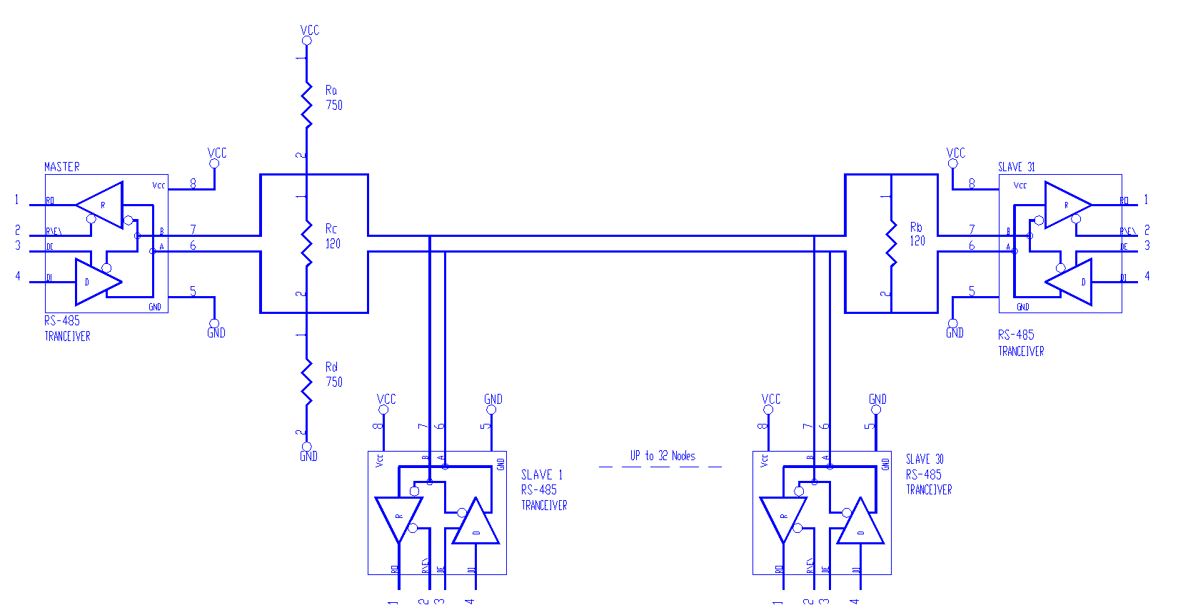
In Murphy’s peer to peer communications the controllers are hardwired together with a single twisted pair cable such as Belden’s 9841 utilizing fail-safe termination. The RS-485 data bus should be terminated at both ends in its characteristic impedance. Stub lengths off the main line should be kept as short as possible. Many of the Murphy Controllers have built-in jumpers to allow configuration of the controller for placement onto the RS-485 data bus. These built-in jumpers are provided as a convenience only and do not have to be used if the bus is otherwise correctly terminated. Note that the terminating resistance should be at the physical ends of the RS-485 data bus and has nothing to do with the controller’s node number. It is customary for the pull up and pull-down resisters to be configured in the Master Controller. You will need to check the data sheets for each individual controller to determine the terminating options available to you.
Wiring to Murphy’s J1708 port
J1708 has been developed by the Truck and Bus Electrical Committee concerning the interface requirements and connecting devices among truck and bus components.
The electrical parameters of the J1708 serial data link are a modification of the EIA RS-485 standard. In some areas J1708 conflicts with RS-485. The J1708 standard serves as the guiding document in such cases. The J1708 bus will support a minimum of 20 standard nodes where each node is comprised of the biasing as described by the J1708 standard.
J1708 is intended for, but not limited to, applications with a maximum cable length to 130 ft (40 m).
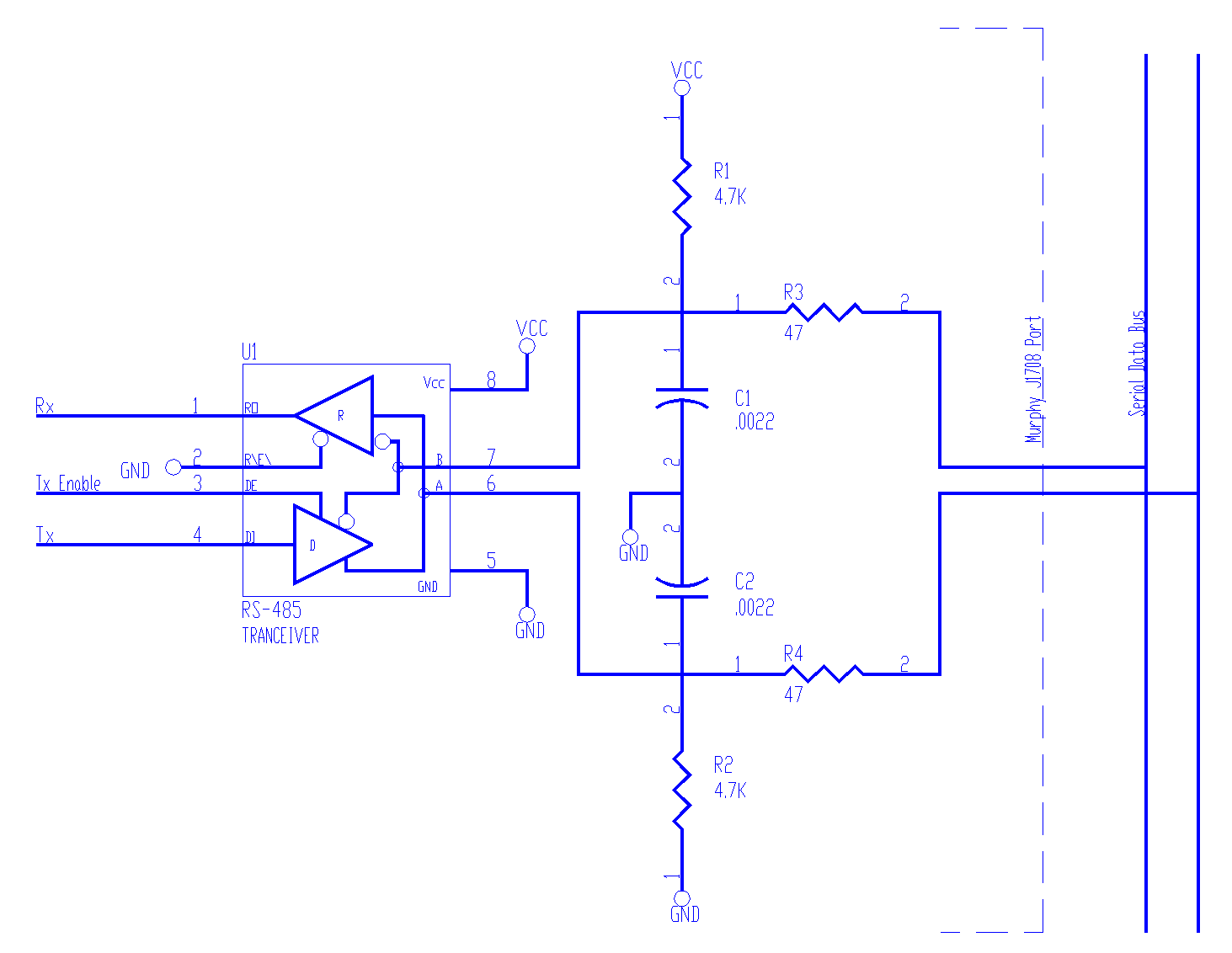
This circuit utilizes standard RS-485 transceivers (less than or equal to one RS-485 unit load) connected to drive the differential data bus to the logic zero state only (unipolar drive). The logic one state (also idle state) is controlled by pull up resistor R1 and pull down resistor R2. The transceiver output impedance, C1 and C2, form the transmit filter for transient and EMI suppression (approximately 6 MHz low pass). R3, C1, R4, C2 form the receive filter for EMI suppression (approximately 1.6 MHz low pass). These parts also form a pseudo line termination at high frequencies. The active (high to low) transition delay is approximately 0.6 us at the receiver with two nodes on the bus and 2.3 us with 20 nodes on the bus. The pass (low to high) transition delay at the receiver remains at 10 us with any number of loads on the bus (up to 20).
While there is no need to configure the J1708 port when connecting to the serial data bus, one must still follow the standard guidelines for wiring a transmission-line.
The RS-485 Standard
The key features are:
*Differential (Balanced) Interface
*Multi-point Operation
*Operation from a single +5 V Supply
*-7 V to +12 V Common Mode Range
*Up to 32 Unit Loads (Transceivers)
*10 Mbps Maximum Data Rate (@40 feet)
*4000 Foot Maximum Cable Length (@100 kbps)
The RS-485 standard specifies the electrical characteristics of the drivers and receivers that could be used to implement a balanced multi-point transmission line (party line). A data exchange network using these devices will operate properly in the presence of reasonable ground drops, withstand line contention situations and carry 32 or more drivers and receivers on the line. The intended transmission medium is a 120 W twisted pair line terminated at both ends in its characteristic impedance.
RS-485 does not specify a connector, cable, or protocol. Higher level standards, such as the ANSI’s SCSI standards and the Society of Automotive Engineer’s (SAE’s) J1708 automotive-communication standard, govern these parameters and reference RS-485 for the electrical specification. EIA-485 drivers can tolerate ground potential differences of up to 7 V from either rail. For lines longer than about five hundred feet, the line and not the driver will dominate the rise time.

Serial Protocol
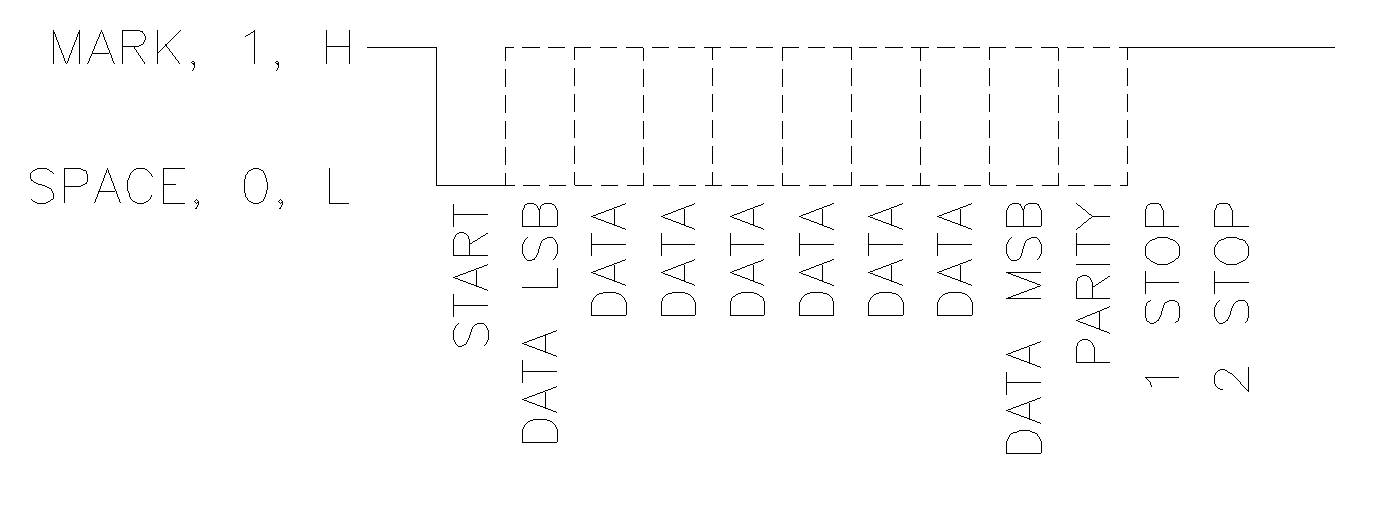
A popular format for low-speed data transmission is an asynchronous protocol. A typical format composed of 12 bits. The start bit initiates the timing sequence. This is detected by a transition from HIGH to LOW. Next are eight data bits, followed by an optional parity bit. Lastly, the line is driven HIGH for one or two bits (stop bits), signifying the end of the character. This format is illustrated below. If another character is to be sent, the next start bit initiates the whole process all over again. However, if this was the last character, the line should remain high until the next start bit, but the active drive is disabled. This presents a problem in multi-point applications, because between data transmissions all drivers are OFF. The bus is a half-duplex bi-directional bus, (as data can flow in both directions), but only one driver should be active at a time. With no active drivers, the line is floating, and receiver outputs are undetermined. There are several solutions to this problem. One is through the use of alternate protocols (software), while the other is a hardware fix. The hardware fix uses external resistors to bias the line HIGH, when all drivers are off. Murphy has chosen to use a hardware fix utilizing fail-safe biasing.
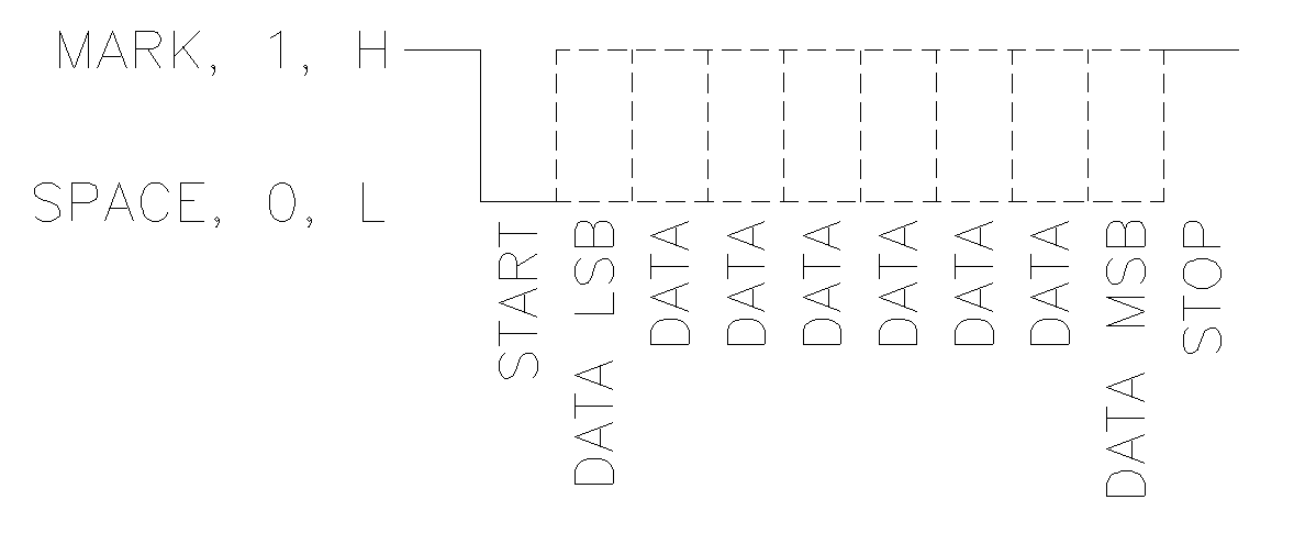
Murphy commonly uses a 10 bit protocol at 9600 bps. You will see this stated as 9600 bps N81. The N means that there is no parity bit. The 8 denotes that there are 8 data bits and the 1 signifies one stop bit. Failure to set the UART to the proper framing will cause the communications network to fail.
Modes and Nodes
Designers frequently ask, “What is the maximum number of transceivers the bus allows?” The standard does not specify a maximum number of transceivers, but it does specify a maximum of 32 ULs. If a transceiver imposes one unit load, the maximum number of transceivers is also 32. You can now obtain transceivers with ½ and ¼ UL ratings, which allow 64 and 128 transceivers. However, these fractional UL devices, with their high impedance input stages typically operate more slowly than do single UL devices. The lower speed is acceptable for buses operating in the low hundreds of kilobits per second, but it may not be acceptable for a 10 Mbps bus.
RS-485 drivers are usually called “60 mA drivers.” The name relates to the allowable loading. Developing 1.5 V across the 60 W termination load (120 W at each end of the bus) requires 25 mA. The worst-case input current of a UL is 1 mA. The worst-case UL input resistance is 10.56 kW, although a frequently quoted incorrect value is 12 kW. Thus, 32 ULs require 32 mA drive capacity. Adding this current to the 25 mA for the terminations yields 57 mA, which rounds up to an even 60 mA. A driver that cannot supply the full 60 mA violates the standard and reduces the bus’s performance. The resulting problems include reduced noise margin, reduction in the number of unit loads or allowable cable length, and limited common-mode voltage tolerance.
A final word of caution: Do not lump too many transceivers too close together. The AC loading, which results mainly from the devices’ pin I/O capacitance (usually 15 pF), can alter the interconnect-medium impedance and cause transmission-line problems. If you think that you have this problem, you may need to find someone who can evaluate the placement of the nodes on the bus. (That is not us! We are not that smart.)
Configurations
Connecting a node to the cable creates a stub, and therefore, every node has a stub. Minimizing the stub length minimizes transmission-line problems. For standard transceivers with transition times around 10 ns, stubs should be shorter than 6 in. A better rule is to make the stubs as short as possible. A “star” configuration is special case and a cause for concern. This configuration usually does not provide a clean signaling environment even if the cable runs are of all equal length. The star configuration also presents a termination problem, because terminating every endpoint would overload the driver. Terminating only two endpoints solves the loading problem but creates transmission-line problems at the unterminated ends. A true daisy-chain connection avoids all these problems.
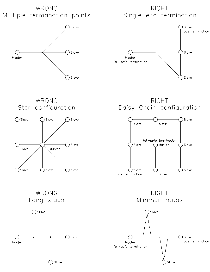
There are times when it will not be convenient to place the master node at the end of the RS-485 bus. When this is the case, you will still need to place the terminating resistor at the end of the cable and provide for fail-safe biasing. One method of accomplishing this is to terminate the cable at each end on the end slave nodes and only using the pull up and pull-down resistor on the master node. Using the pull up and pull-down resistors on the master node are for convenience and standardization only. If you desire, you may place the pull up and pull-down resistors anywhere on the bus, but the terminating resistors must be placed at the physical ends of the cable.
Interconnect Media
The standard specifies only the driver-output and receiver-input characteristics – not the interconnection medium. You can build RS-485 buses using twisted-pair cables, flat cable, and other media, even backplane pc traces. However, twisted-pair cable is the most common. You can use a range of wire gauges, but designers most frequently use 24 AWG. The characteristic impedance of the cable should be 100 W to 120 W. A common misconception is that the cable’s characteristic impedance (ZO) must be 120W, but 100 W works equally well in most cases. Moreover, the 120 W cable’s higher ZO presents a lighter load, which may be helpful if the cable runs are extremely long. Murphy suggests using Belden’s part number 9841 or the equivalent.
Belden’s 9841 cable is a Paired-Plenum RS-485 Computer Cable and consists of 1 pair, 24 AWG, stranded (7x32) and 120 W nominal impedance. TC – Tinned Copper conductors, Foam FEP - Foam Fluorinated Ethylene Propylene Insulation, overall Aluminum Foil-Polyester Tape (Beldfoil) shield with 24 AWG stranded (7x32) tinned copper drain wire and 100% shield coverage plus overall tinned copper Braid Shield with 90% coverage, Foam FEP - Foam Fluorinated Ethylene Propylene jacket. Application Specifications: UL/NEC & CEC C(UL) CMP. Low capacitance for EIA RS-485 applications.
Data Rate vs. cable length
You can transmit data over an RS-485 bus for 4000 ft (1200 m), and you can also send data over the bus at 10 Mbps. But, you cannot send 10 Mbps data 4000 ft. At the maximum cable length, the maximum data rate is not obtainable: The longer the cable, the slower the data rate, and vice versa.
Low speed is generally characterized to be either signaling rates below 200 kbits or when the cable delay (the time required for an electrical signal to transverse the cable) is substantially shorter than the bit width (unit interval) or when the signal rise time is more than four times the one way propagation delay of the cable (i.e., not a transmission line). As a general rule, if the signal rise time is greater than four times the propagation delay of the cable, the cable is no longer considered a transmission line. The rise time (tR) for the Maxim MAX485 RS-485 Transceiver is 3 ns minimum, 20 ns typical, and 40 ns maximum. The delay of the Belden 9841 cable is 1.6 ns/ft.
Worst Case:
*3 ns / 4 = 0.75 ns
*0.75 ns / 1.6 ns/ft = 0.47 ft ( 5-1/16 in )
Typical:
*20 ns / 4 = 5 ns
*5 ns / 1.6 ns/ft = 3.13 ft ( 3 ft 1½ in)
Best Case:
*40 ns / 4 = 10 ns
*10 ns / 1.6 ns ft = 6.25 ft ( 6 ft 3 in )
Termination and Stubs
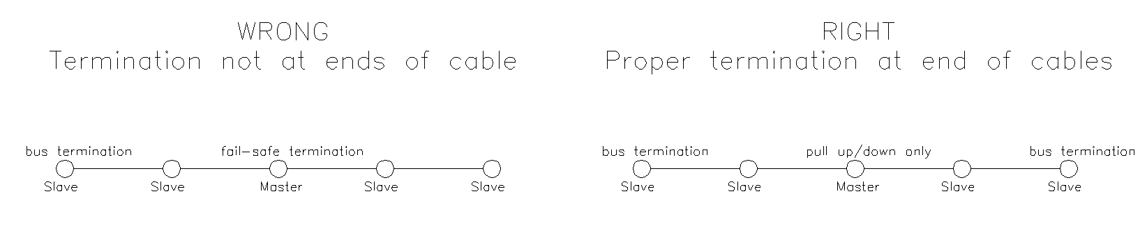
Basic transmission line theory states that a signal propagating down a transmission line will be reflected back towards the source if the outbound signal encounters a mismatch in the line impedance at the far end. Most RS-485 buses require termination because of fast transition, high data rates, or long cables. The purpose of the termination is to prevent adverse transmission-line phenomena, such as reflections. Both ends of the main cable require termination. A common mistake is to connect a terminating resister at each node – a practice that causes trouble on buses that have four or more nodes. The active driver sees the four termination resistors in parallel, a condition that excessively loads the driver. If each of the four nodes connects a 120 W termination resistor across the buss, the active driver sees a load of 30 W instead of the intended 60 W. The problem becomes substantially worse with 32 nodes. If each node includes a 120 W terminating resistor, the load becomes 3.75 W. There may be provisions for termination at every node, but you should activate the termination resistors only at the end nodes (by using jumpers for example).
Keeping a stub’s electrical length below one-forth of the signal’s transition time ensures the stub behaves as a lumped load and not as separate transmission line (Worst case with the MAX485 transceiver is 5-1/16 in.) If the stub is long, a signal that travels down the stub reflects to the main line after hitting the input impedance of the device at the end of the stub. This impedance is high compared with that of the cable. The net effect is degradation of signal quality on the bus. Keeping the stubs as short as possible avoids this problem. Instead of adding a long branch stub, loop the main cable to the device you wish to connect.
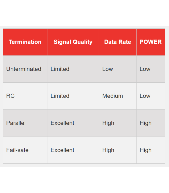
You have several options for terminating an RS-485 bus. The first option is no termination. This option is feasible if the cable is short and if the data rate is low. Reflections occur, but they settle after about three round-trip delays. For a short cable, the round-trip delay is short and, if the data rate is low, the unit interval is long. Under these conditions, the reflections settle out before sampling, which occurs at the middle of the bit interval.
*At 9600 bps each bit is ( 1 s / 9600 bps ) = 104.67 us
*If we allow 25% degradation of the bit signal then we can allow the reflection to ring before settling for ( 104.67 us / 4 ) = 26.04 us.
*This will allow the reflection to travel ( 26.04 us / 1.6 ns/ft ) = 16,276 ft.
*As the reflection will continue to ring for three-round trips regardless of the cable length, the maximum unterminated cable length is ( 16,276 ft / 6 ) = 2,713 ft.
While it may be possible to drive an RS-485 bus over 2,500 ft without termination in some cases, this will not hold true for all cases. As nodes are added to the bus the 1.6 ns/ft value may change. Jitter, noise and other electrical characteristics of your bus may also significantly reduce the allowable unterminated bus length. We do not recommend an unterminated bus because it does not deal with the fail-safe condition of the bus and proper termination of the bus will not hurt the signal.
The most popular termination option is to connect a single resistor across the conductor pair at each end. The resistor value matches the cable’s differential-mode characteristic impedance. If you terminate the bus in this way, no reflections occur, and the signal fidelity is excellent. The problem with this termination option is the power dissipated in the termination resistors. Eliminating all reflections requires that terminating resistor (RT) be selected to match the characteristic impedance (ZO) of the transmission line. As a general rule, however, it is usually better to select RT such that it is slightly greater than ZO. Over-termination tends to be more desirable than under-termination since over-termination has been observed to improve signal quality. RT is typically chosen to be up to 10% larger than ZO. The elimination of reflections permits higher data rates and cable lengths. That is, the higher the data rate the shorter the cable and conversely the lower the data rate the longer the cable.
If you must minimize power dissipation, RC termination may be the solution. In place of the single resistor, you use a resistor in series with a capacitor. The capacitor appears as a short circuit during transitions, and the resistor terminates the line. Once the capacitor charges, it blocks the DC loop current and presents a light load to the driver. Low-pass effects limit use of RC termination to lower data-rate applications, however. In asynchronous applications, parallel termination’s is not able to guarantee receiver fail-safe during idle bus states which in turn makes the system susceptible to errors such as false start bits and framing errors. The primary reason for the RC termination, however, grew out of the need for effective transmission line termination with minimal DC loop current.
Another popular option (and the one chosen by Murphy) is a modified parallel termination that also provides fail-safe bias. Fail-safe biasing provides a known state when all drivers are in TRI-STATE (Hi-Z, OFF). This is especially important in bus configurations that employ more than one driver (transceiver) and is commonly known as a Multi-Point application. The main point to remember is that, if you use termination, you should locate the termination networks at the two extreme ends of the cable, not at every node.
Grounding and shielding
Although the potential difference between the data-pair conductors determines the signal without officially involving ground, the bus needs a ground wire to provide a return path for induced common-mode noise and currents, such as the receivers’ input current. A typical mistake is to connect two nodes with only two wires. If you do this, the system may radiate high levels of EMI, because the common-mode return current finds its way back to the source, regardless of where the loop takes it. An intentional ground provides a low-impedance path in a known location, thus reducing emissions.
Electromagnetic-compatibility and application requirements determine whether you need a shield. A shield both prevents the coupling of external noise to the bus and limits emissions from the bus. Generally, a shield connects to a solid ground (normally, the metal frame around the system or subsystem) with a low impedance at one end and a series RC network at the other. This arrangement prevents the flow of DC ground-loop currents in the shield.
Contention protection
Because RS-485 allows for connecting multiple drivers to the bus, the standard addresses the topic of contention. When two or more drivers are in contention, the signal state on the bus is not guaranteed. If two drivers are on at the same time and if they are driving the same state, the bus state is valid. However, if the drivers are in opposite states, the bus state is undetermined, because the differential voltage in the bus drops to a low value within the receiver’s threshold range. Because you do not know the driver states, you must assume the worst – namely, that the data on the bus is invalid. Note that when using the J1708 biasing, a low state will win when there is contention on the bus.
Special-Function Transceivers
There are several special function transceivers available to handle many of the issues mentioned. But these transceivers must be selected based on each individual bus configuration. To allow for maximum flexibility and minimum engineering Murphy has chosen to implement standard transceivers and use fail-safe biasing.
Fail-safe biasing
The need for fail-safe operation is both the principal application issue and the most frequently encountered problem with RS-485. Fail-safe biasing provides a known state in which there are no active drivers on the bus. Other standards do not have to deal with this issue, because they typically define a point-to-point or multi-drop bus with only one driver. The one driver either drives the line or is off. Because there is only one source on the bus, the bus is off when the driver is off. RS-485 on the other hand, allows for connection of multiple drivers on the bus. The bus is either active or idle. When it is idle with no drivers on, a question arises as to the state of the bus. Is it high, low, or in the state of the last driver? The answer is any of the above. With no active drivers and low impedance termination resistors, the resulting differential voltage across the conductor pair is close to zero, which is the middle of the receiver’s thresholds. Thus, the state of the bus is truly undetermined and cannot be guaranteed.
Some of the functional protocols that many applications use aggravate this problem. In an asynchronous bus, the first transition indicates the start of a character. It is important for the bus to change states on this leading edge. Otherwise, the clocking inside the UART is out of sync with the character and creates a framing error. The idle bus can also randomly switch because of noise. In this case, the noise emulates a valid start bit, which the UART latches. The result is a framing error, or worse, an interrupt that distracts the CPU from other work.
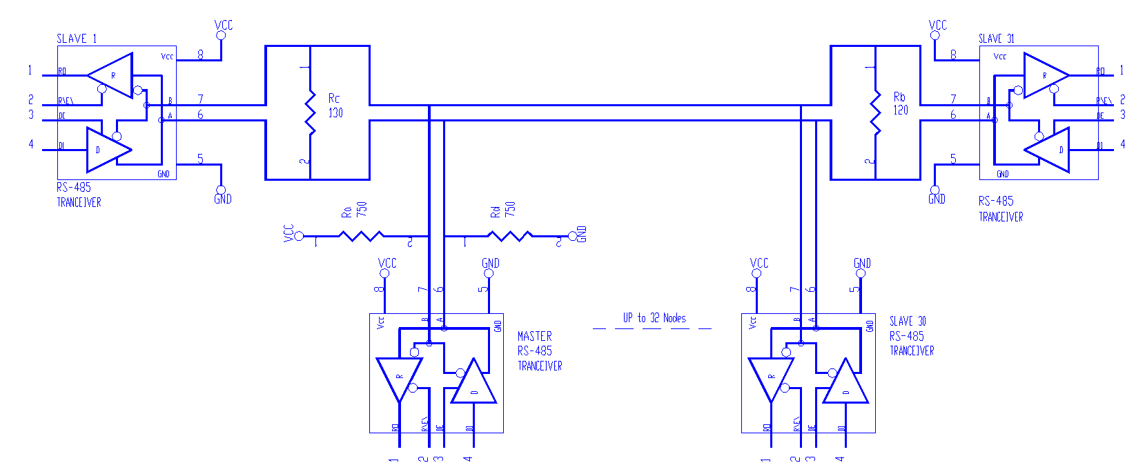
The way to provide fail-safe operation requires only two additional resistors to the parallel termination. At one end of the bus (the master node, for example), connect a pull up and pull-down resistor. This arrangement provides a simple voltage divider on the bus when there are no active drivers. Select resistors so that at least 200 mV appears across the conductor pair. This voltage puts the receivers into a known state. Values that can provide this bias are 750 W for the pull up and pull-down resistors, 130 W across the conductor pair at the fail-safe point and 120 W termination at the other end of the cable. For balance, use the same value for the pull up and pull-down resistors.
Calculation Resistor Values for Failsafe Biasing
The external resistors are selected such that they provide at least a 200 mV (maximum receiver threshold) bias across the line, and not substantially load down the active drive.
In addition, the following guidelines should be met. The pull up resistor (Ra) and the pull down resistor (Rd) should be of equal value. This provides symmetrical loading for the driver. Termination resistor Rb should be selected such that it matches the characteristic impedance (ZO) of the twisted pair cable. If the termination resistor matches the line, Rb = ZO, there will be no reflections. At the other end of the cable, the equivalent resistance of Rc, Ra and Rd should also match the characteristic impedance of the line. In this case Rc is in parallel with Ra plus ( Rc || ( Ra + Rd )). For this equivalent resistance to be matched to the line Rc must be greater than ZO. Rc is typically 10 W – 20 W greater than ZO, but the actual value depends upon the values Ra and Rd. The fail-safe bias (Vfsb) is the potential dropped across the line. Note that this equation neglects cable resistance, and that Rb is in parallel with Rc ( Req = Rb || Rc). Therefore, the fail-safe bias is simply a voltage divider between Req, Ra, and Rd. The worst case occurs at VCC – 5%, Ra and Rd + % tolerance, and Rc and Rb - % tolerance. Under the worst case conditions the fail-safe bias must be greater than 200 mV for the receiver output to be in a guaranteed state.
Example calculations for selecting fail-safe bias resistors:
Note: For this example, we assume the cable has characteristic impedance (ZO) of 120W.
Step 1 Assume that Rc and Rb are equal and are selected to match ZO.
Rc = Rb = ZO = 120W
Step 2 Calculate the equivalent resistance of Rc || Rb.
Rc || Rb = 120W || 120W = 60W
Step 3 Calculate the Pull up and Pull down resistor values knowing that the fail-safe bias is 200 mV, and VCC = 5V.
Vfsb = VCC ( Req / ( Ra + Req + Rd ))
solving for R’ (defined as Ra + Rd)
R’ = (( Req ) VCC / Vfsb) – Req)
R’ = (( 60 W ) 5 V / 0.2 V ) – 60 W = 1440 W
Since Ra and Rd are equal, Ra = Rd = 1440 W / 2 = 720 W
Step 4 Recalculate the equivalent resistance of Rc || ( Ra + Rd )
Rc || ( Ra + Rd ) = 120 W || ( 720 W + 720 W ) = 110 W
Since the equivalent resistance is close (within 10%) to the characteristic impedance of the cable (ZO), no further adjustment of resistor values is required.
However, for the perfectionist, the matched value of Rc can be calculated by setting the following equation to ZO and solving for Rc.
ZO = Rc || ( Ra + Rd )
\Rc = 131 W
Now the equivalent resistance ( Req = Rc || Rb ) becomes 131 W || 120 W = 62 W, which is very close to the original 60 W. Standard value resistors values can be substituted to ease resistor selection, availability, and cost, before recalculating the fail-safe bias potential. Using 5% tolerance table we fine the following standard resistor values:
Ra = 750 W, Rb = 120 W, Rc = 130 W, Rd = 750 W
In order to verify that the selected values meet the criteria the following calculations should be completed:
* Rc || ( Ra + Rd ) = ZO
130 W || ( 750 W + 750 W ) = 120 W
* Req = Rb || Rc
120 W || 130 V = 62 W
* Vfsb = VCC ( Req / ( Ra + Req + Rd ))
5 V ( 62 W / ( 750 W + 62 W + 750 W )) = 200 mV
Based of the example shown above, and a twisted pair cable with characteristic impedance of 120 W, it has been determined that a 750 W pull up and pull down resistor will provide a fail-safe bias of 200 mV. This value could be decreased slightly to provide a greater bias (>200 mV), and to meet worst case power supply and resistor tolerance conditions. However, the value of Ra and Rd should not be reduced too low in order to minimize loading seen by the driver. This example illustrated that the largest values used for the pull up (Ra) and pull down (Rd) resistors should be 750 W. The pull resistors should not be decreased substantially. Because when the drive is active (ON), it is required to develop a minimum of 1.5 V across the cable termination. Use low impedance resistors further loads down the driver, making 1.5 V differential voltage even more difficult to meet.
Note that the fail-safe bias (Power Termination) is only located at one end of the bus. The other end employs a single resistor termination. The fail-safe termination is commonly located on the Master node of a Master/Slave bus configuration.
Conclusion
The termination scheme used will essentially be dictated by the needs of the system. Specifically, the choice of termination will depend upon the system’s transmission requirements. While Murphy has chosen to recommend fail-safe termination of the RS-485 bus, we realize that there are many variables in designing an RS-485 bus and leave it up to the individual designer to choose the proper termination for their project.
---
Article From Our Partner: Enovation Controls "RS-485 the Murphy Way" RS-485 the Murphy Way – Enovation Controls Help Center. 22 July 2022
Contact Us
Phone: 661-272-4700
Email: Sales@MurCal.Com
Follow Us On Social Media


